ERCES Vs. Cellular Explained
ERCES Vs. Cellular Explained: Why First Responders Can't Afford Dead Zones
A plain-language and technically rigorous guide to Emergency Responder Communications Enhancement Systems
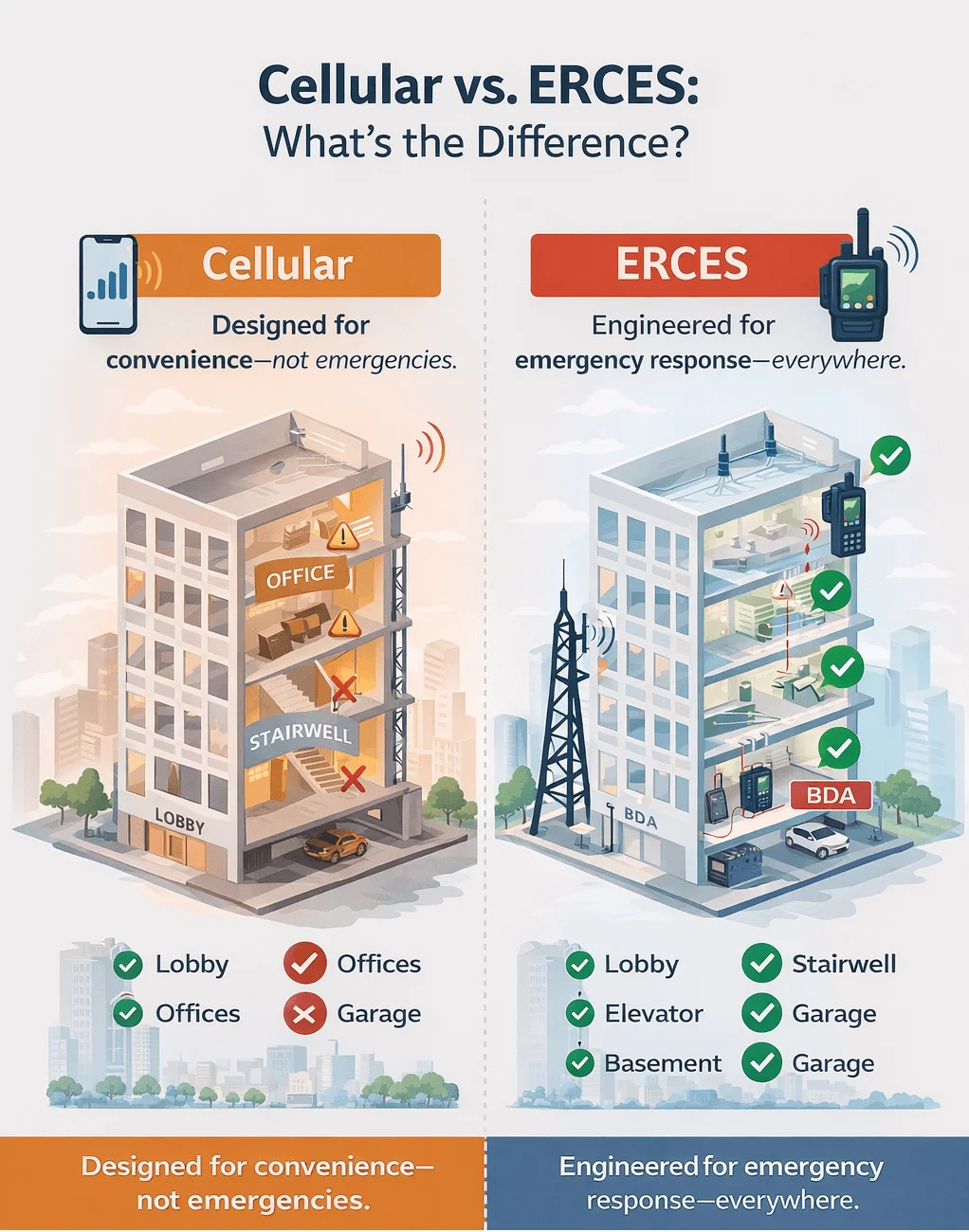
A dropped call in a parking garage is annoying. You lose your place in the podcast, you reschedule the meeting, and you walk outside to call back. It's an inconvenience.
Now put a firefighter in that same parking garage. Radio contact drops. Incident command can't reach the crew on the third subterranean level. The fire is spreading. That's not an inconvenience. That's a life-safety failure.
That distinction—between commercial cellular convenience and emergency radio reliability—is the entire reason Emergency Responder Communications Enhancement Systems (ERCES) exist. It's also why they've moved from a nice-to-have to a hard legal mandate in most U.S. jurisdictions. If your building doesn't have a compliant system, it may not pass inspection. If it has a poorly designed one, your AHJ can shut occupancy down until you fix it.
This post unpacks what ERCES actually is, how the technology works from the antenna on your roof to the radio in a first responder's hand, and what building owners, AEC professionals, and integrators need to understand to get it right the first time.
Why ERCES Exists: The Life-Safety Mandate
Modern buildings are increasingly hostile to radio signals. Dense concrete, rebar, energy-efficient low-e glass, steel-framed curtain walls—all of the materials that make buildings structurally sound and energy-efficient also block or severely attenuate RF signals. This isn't a new problem, but the regulatory response to it is relatively recent.
For decades, public safety communications in buildings relied on whatever signal leaked in from outdoor macro cell towers. For single-story structures in open areas, that worked reasonably well. For high-rises, underground parking garages (see case study further down), tunnels, hospitals, and campus facilities with connected buildings, it often didn't work at all.
The regulatory framework caught up after a series of high-profile incidents where first responders lost communications inside structures. NFPA 1221 (Standard for the Installation, Maintenance, and Use of Emergency Services Communications Systems) and the International Building Code (IBC) now mandate ERCES in a wide range of new construction and renovations. Many jurisdictions have also retroactively required ERCES in existing buildings above a certain square footage or occupancy threshold.
The standard most AHJs enforce: first responder radio coverage must be sufficient on 95% of the building's area on each floor, and 99% in critical areas like stairwells, elevator shafts, fire command centers, and areas of refuge.
The Authority Having Jurisdiction (AHJ)—typically the local fire marshal or fire department—is responsible for enforcement. The building owner is responsible for installation and ongoing maintenance. That responsibility doesn't transfer to the tenant, the contractor, or the integrator once the certificate of occupancy is issued. It stays with the building.
FCC 47 CFR 90.219 governs the technical parameters for signal boosters used in public safety applications. Compliance isn't optional—it's a condition of lawful operation. Boosters that aren't type-accepted under FCC rules, or that operate outside permitted parameters, can be ordered off the air.
How ERCES Works: Three Core Components
At its core, an ERCES is a system that takes a public safety radio signal from outside a building, amplifies it, and distributes it throughout the interior—then sends communications back out with equal reliability. It works in both directions simultaneously. Think of it as a two-way translation layer between the outdoor radio network and the interior of a building.
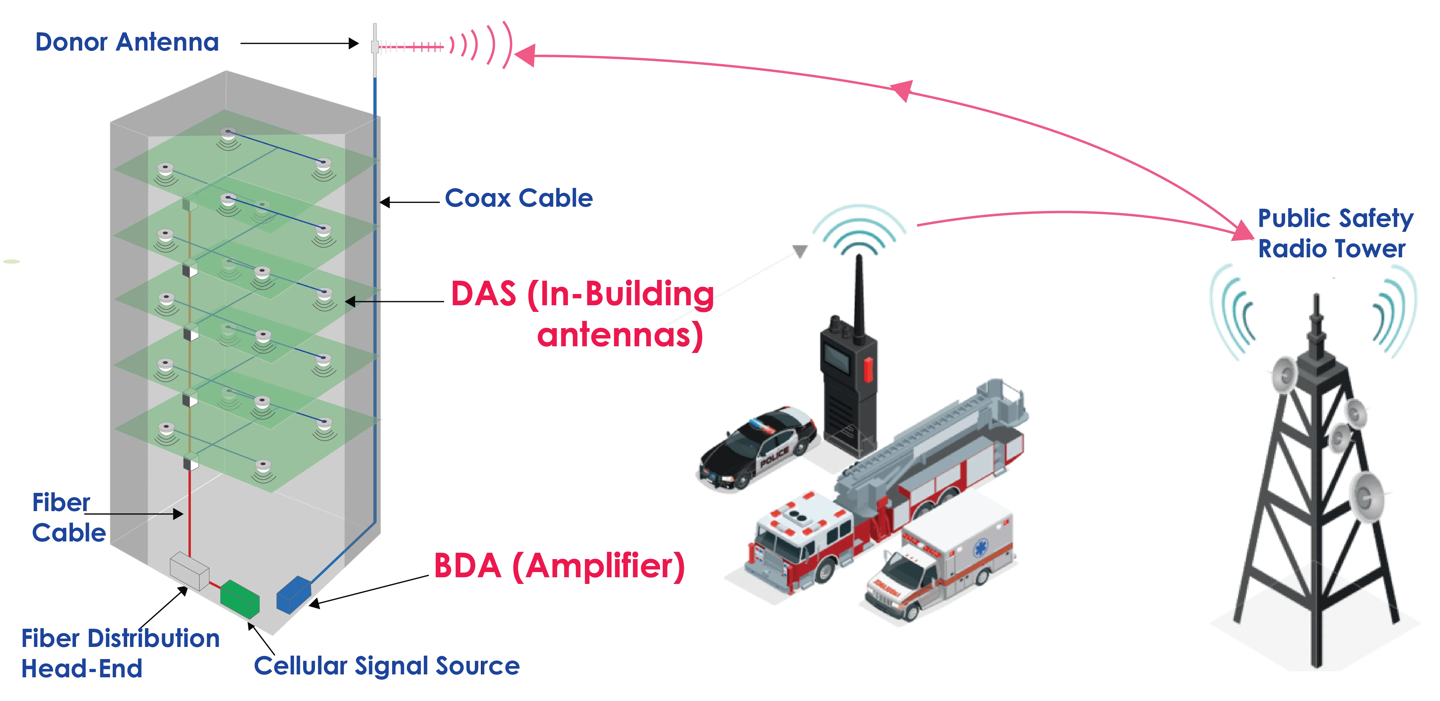
The system has three essential components: a Bi-Directional Amplifier (BDA), a Distributed Antenna System (DAS), and an RF coverage grid test conducted to verify the system actually performs to code.
Component 1: The Bi-Directional Amplifier (BDA)
The BDA is the engine. It receives a radio signal from the outdoor public safety network through a donor antenna—typically mounted on the roof with a clear line-of-sight to the nearest tower—amplifies both the inbound (downlink) and outbound (uplink) signals, and interfaces with the indoor distribution system.
The term 'bi-directional' is critical. A firefighter's portable radio needs to both receive transmissions from command and transmit back. A one-way boost doesn't serve public safety. The BDA processes both paths with equal care.
What separates a public safety-grade BDA from a consumer signal booster you can buy online is precision, selectivity, and regulatory compliance. Public safety BDAs are designed to pass specific frequencies without interfering with adjacent channels. They're built to FCC type-acceptance standards. And they include automatic gain control (AGC) circuitry that prevents feedback oscillation—a condition where the amplifier effectively shouts into its own ear and corrupts the network.
The industry standard for antenna isolation: BDA gain + 15 dB. For an 80 dB BDA, that means 95 dB of isolation is required between the donor antenna and the nearest indoor antenna. This prevents oscillation and keeps you out of FCC enforcement territory.
BDA technology has evolved through three generations, each with different trade-offs:
Basic Broadband BDAs (FCC Class B): These amplify an entire frequency band. They're the simplest architecture—no internal frequency conversion. The trade-off is poor out-of-band rejection, which creates interference risk in dense urban environments where adjacent channels from other services may bleed in. In rural or suburban deployments where the radio frequency (RF) environment is clean, they work well.
Analog RF Boosters: These add an internal heterodyned section—a down-conversion and up-conversion process that enables much sharper filtering at a lower intermediate frequency (IF). The result is better adjacent-channel rejection, tunability across the band, and the ability to pass specific sub-bands. The components involved are commodity-grade, so the cost premium over basic BDAs is modest.
Digital Filter RF Boosters (FCC Class A): The current state of the art. The IF signal is sampled by a high-speed A/D converter, filtered entirely in the digital domain using Discrete Prolate Spheroidal (DSP), then converted back to analog RF. Current-generation digital boosters support up to 24 independently tuned filter channels, per-channel AGC, and remote programmability. They can be configured as Class A (channel-selective), Class B (broadband), or a mix—making them the most flexible option for complex or evolving network environments.
One technical consideration that's often underestimated: propagation delay. Narrowband filters introduce more delay than wideband filters—a function of basic filter physics. For analog systems with Phase 1 P25 modulation, the maximum allowable relative delay before signal degradation is 33 microseconds. For Phase 2 P25, that drops to 15 microseconds. Most digital boosters operate at around 5 microseconds for wideband configurations. Narrowband configurations can exceed 50 microseconds—which requires careful coverage design to ensure no overlap zones exist where the direct and delayed signals meet at equal levels.
Component 2: The Distributed Antenna System (DAS)
The DAS is the distribution network—the infrastructure that takes the amplified signal from the BDA and delivers it to every corner of the building that needs coverage. It's how you get signal to the parking garage three levels underground, the stairwell in the building core, and the mechanical room with no windows.
There are two fundamentally different approaches to DAS architecture, and choosing between them is one of the most consequential design decisions in an ERCES project.
Passive DAS uses coaxial cables, splitters, couplers, and passive antennas to distribute signal. No active electronics in the distribution path—the signal travels from the BDA through coax to each antenna location. It's simpler to install, easier to troubleshoot, and less expensive for smaller buildings. The limitation is physics: coaxial cable attenuates signal, and those losses increase with length and frequency. For 50-ohm coax, maximum practical run lengths are typically under 1,000 feet before signal levels become marginal. This makes passive DAS the right choice for buildings up to roughly 150,000 square feet, depending on layout and construction.
Active DAS (RF-over-Fiber) replaces long coaxial cable runs with fiber optic links. The signal is converted to light at the BDA head-end, transported over fiber to remote hub units distributed throughout the building, then converted back to RF for the final short coax run to each antenna. Fiber doesn't attenuate the way coax does—active DAS introduces zero distribution loss for any fiber run length. This makes it the only practical choice for large campuses, tall high-rises, or any deployment where antenna locations are more than 1,000 feet from the BDA.
Active DAS comes at a cost premium. Each remote hub unit requires 110 VAC power, and the head-end equipment adds complexity. For a campus deployment connecting multiple buildings, you're looking at 4-6 single-mode fibers per remote hub run as home-run paths back to the BDA—with at minimum 2 in use and the rest as spares. Fiber optic connectors must be SC-APC or FC-APC specification. Standard SC connectors are not acceptable for this application.
Design rule of thumb: passive DAS for buildings under 150,000 sq ft with manageable cable runs; active DAS for anything larger, anything multi-building, and any installation where a remote hub location is more than 1,000 feet from the BDA.
Component 3: RF Coverage Verification
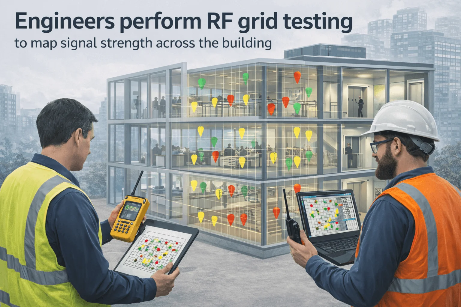
A well-designed ERCES that hasn't been tested isn't a compliant ERCES. Most jurisdictions require a formal RF coverage test before the system can be accepted. The test protocol is straightforward: a walk-through of the building with a calibrated RF meter, recording signal levels at defined grid points on each floor, in stairwells, elevator cabs, and critical areas.
The results must demonstrate that the system meets the coverage thresholds required by the AHJ—typically 95% area coverage with a minimum signal strength of -95 dBm on the downlink and a minimum DAQ (Digital Audio Quality) level on the uplink. Failing the test means going back to the design to identify gaps, adding antennas, adjusting gain settings, or relocating components.
Coverage testing isn't a one-time event. Most AHJs require annual re-testing to verify the system continues to perform as designed. Building renovations that alter the RF environment—new walls, new mechanical systems, tenant build-outs—can invalidate a prior test. Building owners need to treat ERCES as ongoing infrastructure, not a one-time installation.
Real-World Cellular Application: The Austin Underground Parking Case
A case study on how a consumer centric application of cellular boosting can create a safe environment in one that is often contradictory. First responders need the same application, but of a different nature.
A commercial real estate company in Austin, Texas was operating a shared underground parking garage serving both an apartment building and a business high-rise. Three floors below grade. Dense concrete construction. No meaningful signal from any carrier.
The problem wasn't just inconvenient for tenants and visitors—it created a safety liability. And the company wanted to deploy a new parking application to reduce payment kiosk wait times and improve the garage experience. Neither goal was possible without reliable cellular coverage throughout all three levels.
HCI performed a site survey measuring signal strength from all carriers and identifying any structural or regulatory constraints. Based on that analysis, the Cel-Fi QUATRA solution was selected and deployed—a system purpose-built for large-capacity multi-carrier environments like this one. Flat-panel boosters were installed at each underground level, fed by a rooftop donor antenna with clear line-of-sight to nearby carrier towers.
The outcome was measurable and immediate: coverage went from virtually no signal to full bars on all carriers across all three levels. The coverage quality inside the garage exceeded what users experienced at street level outside. The parking application deployed successfully. The operations manager's summary was succinct: 'The solution HCI recommended was perfect for what we needed. All three levels of the garage were covered, and the quality of the install and cell coverage is outstanding.'
Underground and below-grade spaces are among the most common ERCES failures in existing buildings—and among the easiest to solve with proper system design. The physics of RF signal penetration below grade make passive DAS or active DAS essentially mandatory in these environments.
What Building Owners and AEC Professionals Need to Know
If you're responsible for a building—as an owner, developer, architect, or general contractor—here's what ERCES compliance actually means for you in practice.
It's your legal responsibility. The AHJ enforces ERCES requirements on the building owner, not the tenant. Non-compliance can result in failed inspections, delayed certificates of occupancy, and mandatory remediation on existing buildings. The fines and enforcement actions come to you.
Design it early. ERCES is far less expensive and disruptive to install during new construction than as a retrofit. Conduit runs, equipment room allocation, rooftop antenna penetrations, and electrical service to remote hub locations all need to be coordinated with the building design. Bringing ERCES into a project after construction documents are complete costs more and compromises the quality of the installation.
Use licensed professionals. The NPSTC and FCC are explicit on this point: even small ERCES installations should be designed and deployed by experienced, licensed engineers. A hasty installation of an undersized broadband booster can cause more problems than it solves, violating FCC rules, and providing coverage that fails when you actually need it. The savings from cutting corners on design aren't worth the liability.
Budget for ongoing compliance. Annual testing, battery backup verification, and coordination with the AHJ are ongoing costs. Factor them into your facility management budget before the system goes live, not after the first failed annual inspection.
The Bottom Line
ERCES is infrastructure. Not marketing, not a value-add—infrastructure as fundamental to a building's function as fire suppression and emergency egress. The regulatory environment has made that official, and enforcement is only getting stricter.
The good news: when designed correctly and installed by qualified professionals, ERCES works. It reliably extends public safety radio coverage into every corner of a building, survives real emergencies when the demand on the system is highest, and gives first responders the communications reliability they need to do their jobs.
A firefighter losing radio contact in a stairwell isn't an RF engineering problem. It's a design failure. And it's preventable.
If you're designing, building, owning, or managing a structure where ERCES is required—or where it should be—the right time to address it is before occupancy, not after an incident.
About HCI
HCI partners with building owners, developers, and property managers as consultants and integrators to design, deploy, and maintain ERCES and commercial DAS solutions. We work with our customers to solve their communications goals—not to sell them equipment they don't need.
HCI is the leading Motorola Solutions Channel Partner in Houston , Texas. We have been serving our clients for over 40 years.
Texas Security License: B24122601
Navigation
Popular Links
Contacts
Locations:
HCI
1105 Industrial Blvd.
Sugar Land, TX 77478
281-491-1616
HCI Dallas (Formerly Blair Communications, Inc.)
11407 Goodnight Lane
Dallas, TX 75229
972-247-4901
E-mail: Contact Us
